

How To Craft A Solar Tablet
Nov 20, 2015
How to build a solar-powered USB charger for phones and other small devices
correspondent: Netia McCray
Part Two in a two-function series. Part Ane: How to build a solar-powered electronic excursion .
Last twelvemonth, our squad at Mbadika was working on an idea to aid aspiring young innovators and entrepreneurs acquire the basics of production design and development. Based on our experience, hands-on learning of hardware and electronics were the lessons that stuck with us. We've spent the by twelvemonth developing a DIY (do-it-yourself) kit for youth to gain hands-on experience with electronics and hardware.
Our inaugural DIY kit is a Solar USB Charger to introduce youth to electronics prototyping and solar engineering.
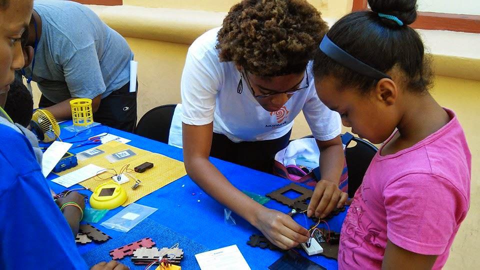
Kids in a Mbadika Workshop gather their Solar USB Charger.
Nosotros've spent the past few months testing our Solar USB Chargers with youth in South Africa, which is how we met EduGreen and started our partnership. Subsequently receiving amazing feedback from our workshop participants, nosotros've decided to further develop our Solar USB Charger kit in social club to launch in South Africa later on this yr.
The following is a step by footstep guide to edifice the Solar USB Charger nosotros debuted at Maker Faire Africa 2014 in Johannesburg.
Materials
- 0.5 Watt Solar Panel
- Mini Breadboard
- DC to DC Booster Excursion: 0.9V to 5V Circuit
- Mini Slide Switch SPDT
- 2xAA Battery Holder
- 2xAA Rechargeable Batteries
- N914 Diode
- (half dozen) Jumper Wires (Recommended Length: 125mm)
- (2) 3mm LEDs
- Optional: Solid Core Wire
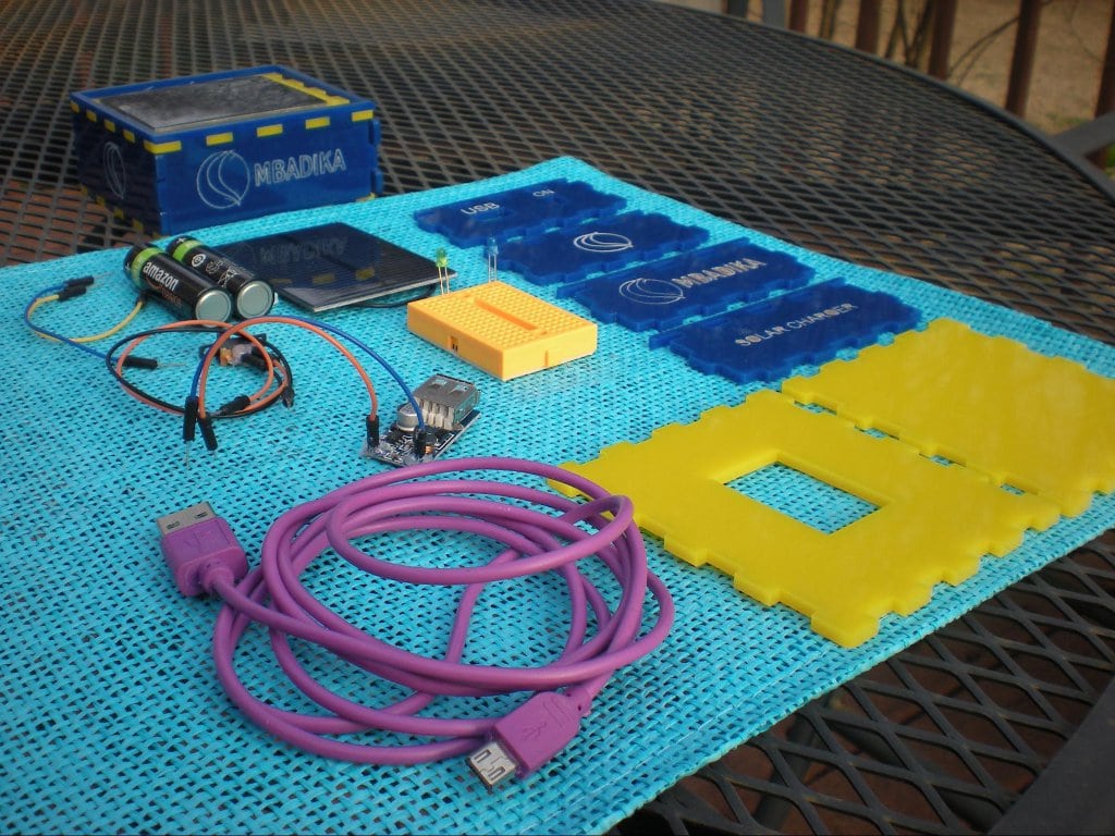
This is the layout of Mbadika Solar USB Charger components.
Hint: Components with an asterisk (*) should be prepared for use with a breadboard by soldering solid core wire leads to the positive (anode) and negative (cathode) leads of the electronic component. Our Solar USB Charger kits include electronic components with jumper wires soldered and hot glued instead of a typical solid core wire.
WE Practice Non RECOMMEND using jumper wires, despite being great to utilise with breadboards, because if the soldering iron touched the plastic component of the jumper wire, it tin can release toxic fumes.
Give your Solar Console a Examination Run
Nosotros will be using a LED in order to test our Solar Panel.
A basic LED has two leads, a positive (anode) and negative (cathode) atomic number 82. In order to identify the positive and negative leads of a LED, i pb is shorter than the other. The longer lead is the positive (anode) lead and the shorter pb is the negative (cathode) lead.
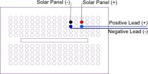
Analogy 1. Breadboard layout for testing Solar Panel.
Identify the breadboard in the mural orientation, every bit shown in Illustration 1.
If your Solar Console does not already take exposed solid cadre wire ends, attach solid core wires to the positive and negative leads of the solar panel via soldering in order to insert the Solar Panel into the breadboard electronic excursion.
For the purpose of our kits, we use Solar Panels with a wire connection component. The wire connectedness component allows the user to extend the positive and negative leads of the Solar Panel via the insertion of jumper wires in the corresponding holes.
Place your Solar Panel and LED leads in the holes of the breadboard, equally shown in Illustration ii. If your LED lights upwards, your Solar Panel is functioning.
Pace 1: The DC to DC USB Booster Circuit
The DC to DC USB Booster Circuit volition allow for you to charge your USB powered device through increasing the DC Voltage from ii.4V to 5V, which is platonic for charging small electronic devices such as basic smartphones, mobile players, and feature phones.
Note:One AA bombardment is 1.2V. Since our circuit uses two AA batteries, our circuit voltage is 2.4V.
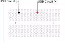
Illustration ii
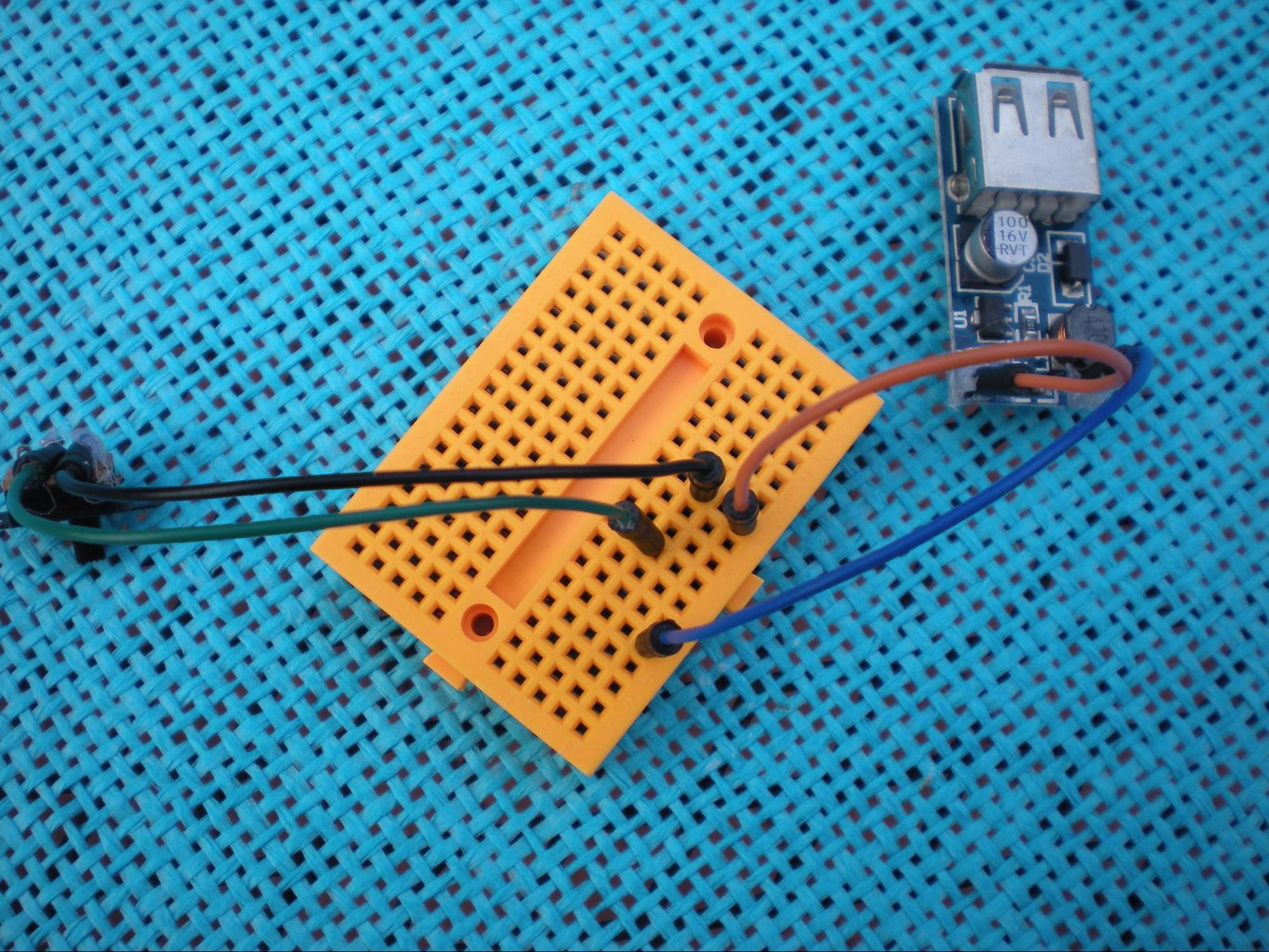
Place your DC to DC USB Booster Circuit leads in the holes of the breadboard as shown in Illustration 2.

Breadboard layout with USB DC to DC Booster Circuit.
As shown in the photo, your breadboard layout should be fairly uncomplicated.
Hint: When inserting electronic components in a breadboard, it is ideal to place the leads of your electronic components in the same row. Placing your electronic components in the same row allows for like shooting fish in a barrel trouble-shooting in the future.
Hint: If you are comfy you can conform your electronic component in whichever column or row. All the same, the electronic component leads illustrated in a item column in the following illustrations must be in THE Aforementioned Column and on the Same SIDE (beneath or above the hollowed middle section) of the breadboard for the electronic circuit to part.
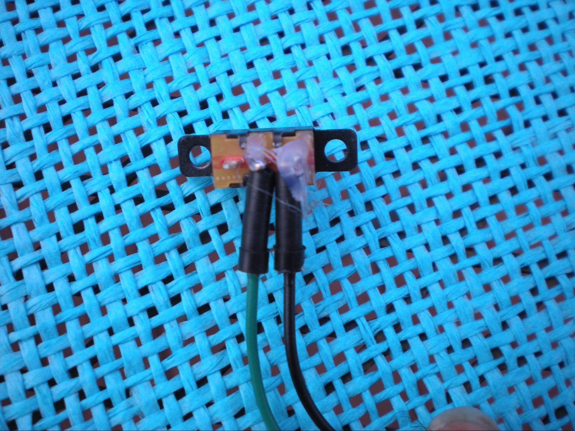
Mini Slide Switch setup with soldered jumper wires and hot glue.
Step two: The Switch
The Mini Slide Switch is an electronic component that will allow for you to control when your Solar USB Charger device is on or off.
This step can be a bit tricky in terms of identifying the middle pin and the terminate pin. As the photograph shows, the center pin is the centre component of the mini slide switch while the end pivot is either the left or right pin.
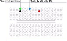
Analogy three
Once yous accept your Mini Slide Switch pin and leads selected and prepared, place your Mini Slide Switch in the breadboard as shown in Illustration 3.
Breadboard layout with Mini Slide Switch.
At this stage, your breadboard should expect like the 1 in this photograph.
Pace iii: The Battery Holder
The Battery Holder will exist the private storage facility for the power accumulated from the Solar Panel too every bit a backup power source when your Solar Panel cannot charge your USB powered device straight.
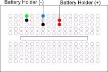
Illustration 4. Breadboard layout for 2xAA Battery Holder.
Place your Battery Holder equally shown in Illustration 4.
Now your breadboard should start to expect like this.
Step four: The N914 Diode
The N914 Diode is a signal diode is an electronic component that prevents current in your Solar USB Charger circuit to travel in the contrary direction or in essence un-charge your electronic device.The N914 Diode is recognizable considering information technology has a red fundamental trunk with a thin black line on i end.
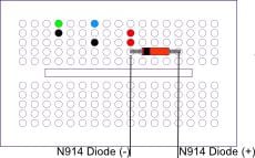
Illustration five
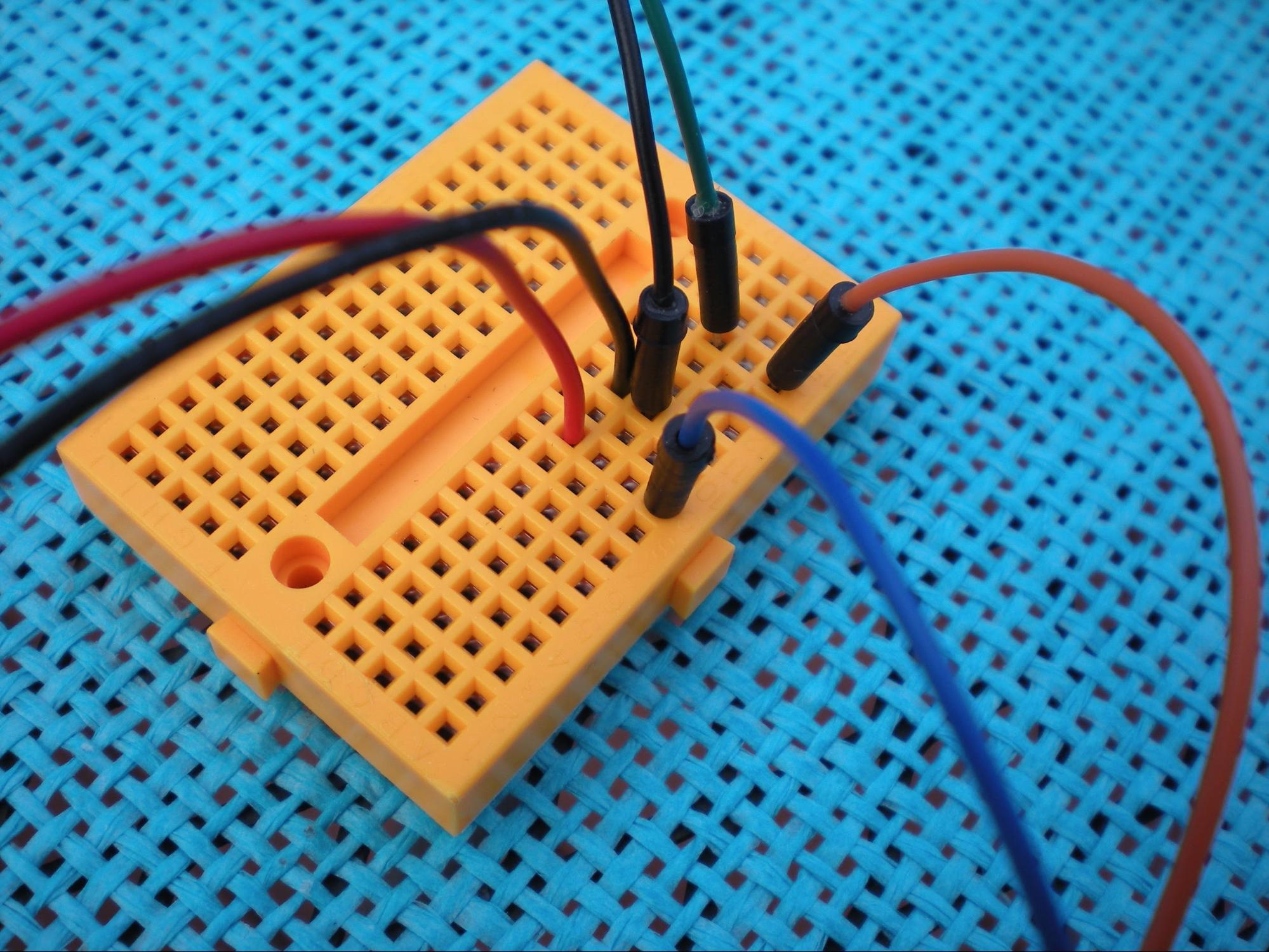
Place the N914 Diode in your breadboard every bit shown in Illustration five.

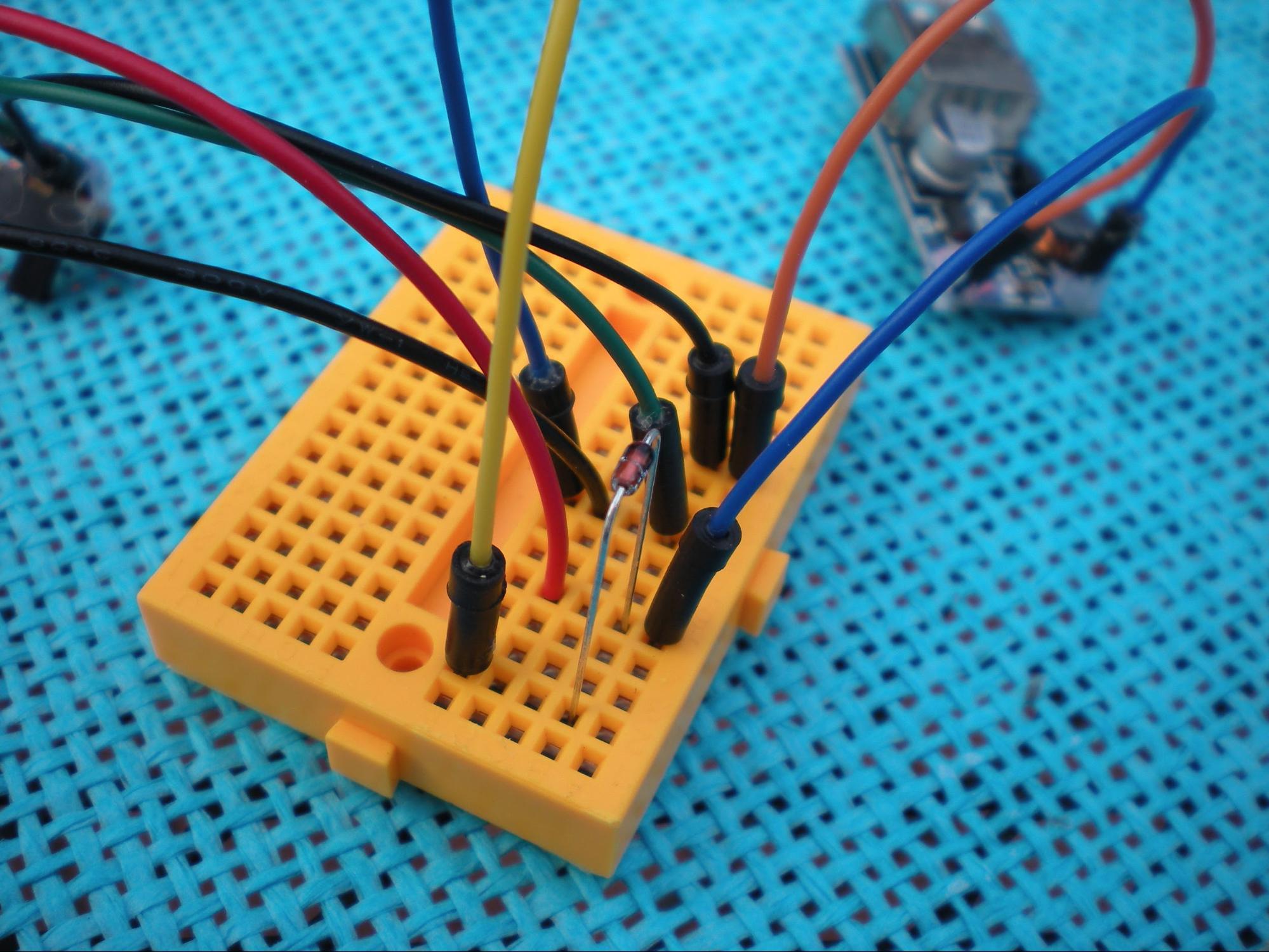
Illustration 6. Breadboard layout with N914 Diode.
Ensure the Negative Pivot (the end of the electronic component with a sparse black line) of the N914 Diode is in the same column as the positive lead of the Battery Holder and DC to DC USB Booster Circuit, every bit shown.
At present, you are gear up for the terminal step in your Solar USB Charger build.
Step 5: The Solar Panel
Place your Solar Panel in your breadboard as shown in Illustration half dozen.
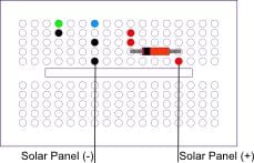
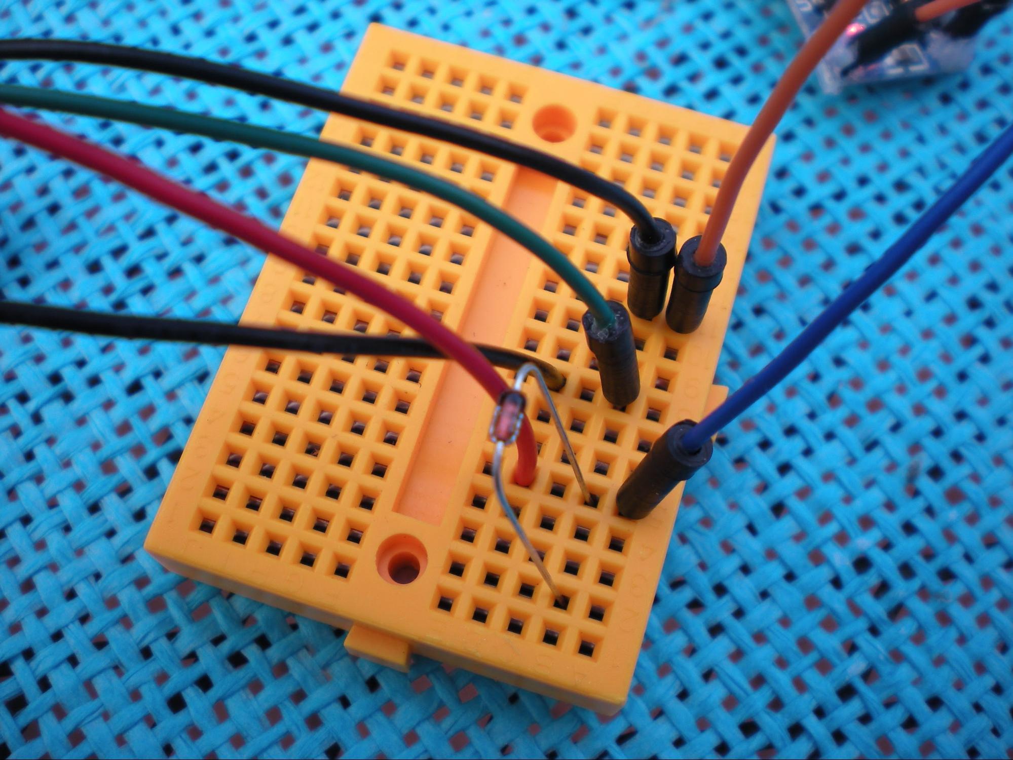
Illustration vii
DOUBLE Cheque YOUR CIRCUIT.
Make sure your circuit matches the breadboard excursion diagram in Illustration seven and looks like to the one pictured here.
DOUBLE CHECK YOUR CIRCUIT ONE LAST Time.
Pace 6: Examination Driving your Solar USB Charger
Place your AA Rechargeable Batteries in your Battery Holder.
Warning: If your circuit begins to smoke or the plastic components in the circuit start to melt, IMMEDIATELY remove all of the components from the breadboard as quickly every bit possible and if possible remove the rechargeable batteries from the battery holder.
At present…slide your Mini Slide Switch…the red LED on your DC to DC USB Booster Circuit will turn on and…Voila!
You are ready to plug in your USB cable and charge your small electronic device.
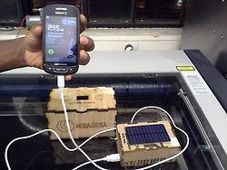
Our first Solar USB Charger prototype comes to life.
Note: The Solar USB Charger will not power Apple devices, smartphones with big lithium ion batteries, or tablets.
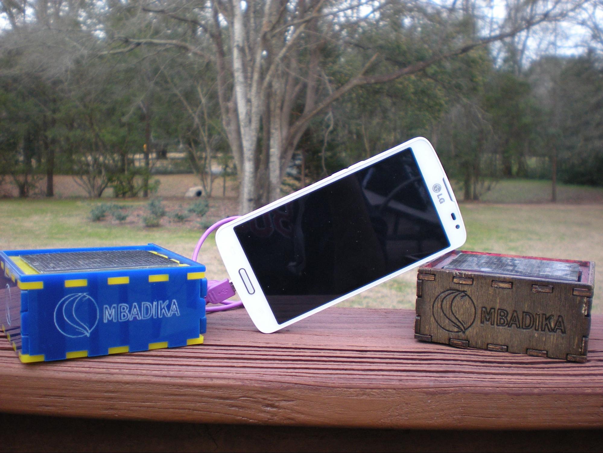
Mbadika Solar USB Charger for Mobile Devices Acrylic and Plywood versions.
Further Steps
You tin can build an enclosure for your Solar USB Charger similar these that we make.
For our Solar USB Charger Kits for youth, we use a laser cutter on MIT campus in order to cutting LEGO inspired enclosures from plywood and acrylic. If you have access to a laser cutter, you tin notice tons of open-source laser cutting files (typically Adobe Illustrator or Corel Draw files) to download and use to create fun enclosures for your Solar USB Charger. However, we are enlightened the majority of the planet does not have access to such facilities and there are other solutions to showcase your new solar build.
Our favorites are fabricated from small plastic storage containers or Altoids tins. A young man MIT alum, Ladyada of Adafruit Industries developed a Altoids Tin enclosed USB Charger Kit called the MintyBoost that has become a huge hit in the maker customs. If your solar panel is modest enough, you lot can have the solar panel be attached on the outside of the Altoids Tin for charging and stored in the tin when not in apply.
Given the solar enclosure will exist exposed to large amounts of sunlight, we would not suggest using cardboard or a paper-based product as your solar enclosure.
Soldering
As our Solar USB Charger kit is focused on introducing youth to electronic prototyping via a breadboard, we try to minimize soldering as much every bit possible.
If you lot would like to create a more permanent Solar USB Charger through soldering your components, Joshua Zimmerman has an excellent Instructables on a soldered version of the Solar USB Charger nosotros've illustrated above.
Are you lot shopping for components to make your very own? Here are some places to purchase materials:
- Dark-brown Dog Gadgets
- SparkFun Electronics
If you need a trivial more help to go started, check out the Solar USB Kit 1.0 by BrownDog Gadgets.
More resources
- SparkFun Electronics Tutorials on Diodes
- SparkFun Electronics Tutorials on Resistors
- SparkFun Electronics Tutorials on Capacitors
- SparkFun Electronics Tutorials on Transistors
tags : construction guide, construction transmission, DIY, do-it-yourself guide, phone, smartphone, solar, solar charger, Solar Ability, solar USB charger
Source: https://www.engineeringforchange.org/news/how-to-build-a-solar-powered-usb-charger-for-phones-and-other-small-devices/
0 Response to "How To Craft A Solar Tablet"
Post a Comment